The Engineering Imperative: Why Basic DC Supplies Fail in Terrestrial Photovoltaic Simulation
Understanding the physics of non-linear PV solar array behavior, high-speed dynamic Maximum Power Point Tracking (MPPT), and low-capacitance power hardware execution.
As global power grids accelerate integration of utility-scale renewable energy, solar string and central inverters face unprecedented performance, efficiency, and compliance scrutiny. Traditional programmable DC power supplies—designed with standard constant-voltage (CV) or constant-current (CC) control loops—are fundamentally incapable of emulating the non-linear output characteristics of terrestrial silicon, thin-film, bifacial, and perovskite solar arrays.
A standard programmable DC power supply exhibits high output capacitance designed to minimize voltage ripple. However, when connected to a Maximum Power Point Tracking (MPPT) inverter, this large output capacitance acts as a massive energy reservoir. When the inverter’s high-frequency perturb-and-observe (P&O) or incremental conductance algorithm alters its effective impedance to track the peak power point, the power supply's output capacitance discharges rapidly into the inverter. This distorts the true current-voltage ($I-V$) curve, introduces artificial resonance, destabilizes the inverter's control loop, and yields false efficiency measurements.
Architectural Information Gain: The Silicon Carbide (SiC) Low-Capacitance Edge
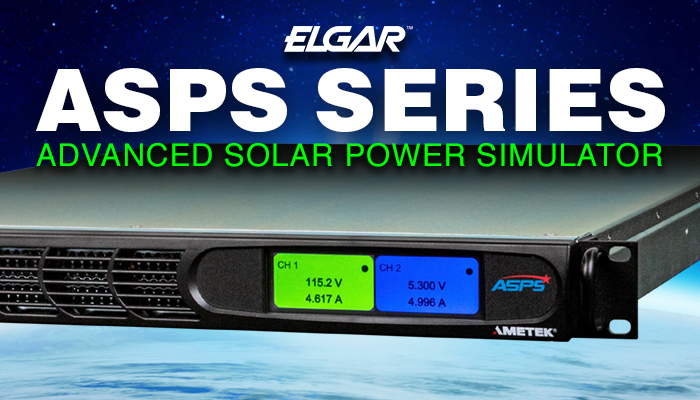
AMETEK’s Terrestrial Photovoltaic Simulators (such as the Elgar TerraSAS ETS Series and ASPS Series) utilize custom low-capacitance output filter topologies integrated with ultra-fast DSP-driven digital control loops. By reducing output capacitance up to 100 times compared to standard DC power supplies, our PV simulators can execute microsecond-level $I-V$ curve updates, accurately simulating rapid cloud-cover transitions, micro-climate shading, and extreme ambient temperature shifts without distorting the inverter's MPPT tracking loop.
Mathematical Physics of Solar Array Emulation
To accurately simulate a terrestrial solar cell or module string, an advanced PV simulator must recalculate the single-diode or double-diode mathematical model in real time. The terminal current ($I$) as a function of terminal voltage ($V$) is governed by the non-linear transcendental equation:
I = I_ph - I_0 * [ exp( (q * (V + I * R_s)) / (n * k * T) ) - 1 ] - (V + I * R_s) / R_sh
Where $I_{ph}$ represents photo-generated current (proportional to solar irradiance $E_g$), $I_0$ is the diode reverse saturation current, $R_s$ is the internal series resistance, $R_{sh}$ is the shunt resistance, $n$ is the diode ideality factor, $k$ is the Boltzmann constant, and $T$ is the cell junction temperature in Kelvin.
AMETEK’s specialized terrestrial solar array simulation software embedded in our FPGA architecture recalculates this equation at lookup rates exceeding 100 kHz. This ensures that whether testing a residential microinverter operating at 60V DC or a multi-megawatt central utility inverter operating at 1500V DC, the simulator tracks the theoretical open-circuit voltage ($V_{oc}$), short-circuit current ($I_{sc}$), maximum power voltage ($V_{mpp}$), and maximum power current ($I_{mpp}$) with sub-0.05% accuracy.

Advanced power semiconductor test bench evaluating fast switching dynamics under simulated solar array power profiles.