Power Electronics Blog & Articles
In-depth technical guides, engineering innovations, and testing methodologies from AMETEK Programmable Power specialists.
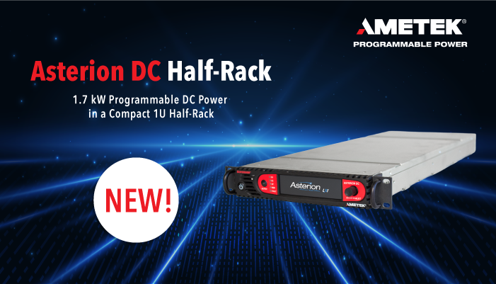

Discover best practices for bidirectional power supply integration and regenerative grid simulation testing.
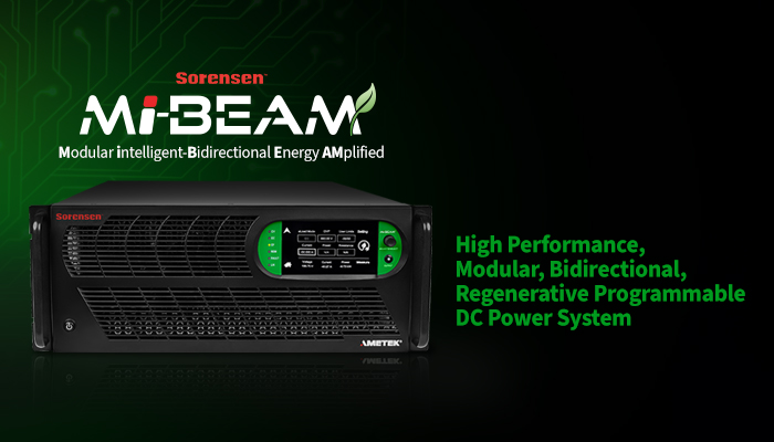
Learn how advanced MPPT algorithms and solar array simulators improve power subsystem testing for aerospace applications.
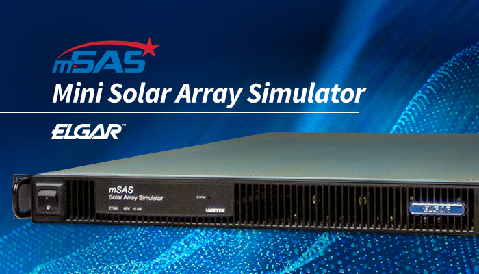
Space Solar Array Simulators are becoming essential tools for spacecraft manufacturers, research laboratories, and satellite integrators worldwide. These systems reproduce sunlight, electrical output, and changing orbital conditions inside controlled test environments. They help engineers evaluate solar panels before launch, when repair is rarely practical.
A strong simulator must deliver stable irradiance, accurate spectral matching, and repeatable current-voltage measurements. It should also support different array sizes, test distances, and automation platforms. In real laboratories, engineers may compare a small triple-junction panel under simulated sunlight, then repeat the test after thermal cycling. Tiny calibration errors matter. They can distort efficiency results and weaken design decisions.
John C. Mankins, a former NASA engineer and respected space solar power researcher, has stated, “The technical challenges are substantial, but none appears to be insurmountable.” His observation fits the simulator market well. Reliable equipment turns difficult testing into measurable evidence. However, no ranking is perfect. A simulator that performs well for a university laboratory may not suit a commercial spacecraft program. Buyers must examine lamp lifetime, uniformity, calibration records, cooling requirements, service support, and regional compliance.
Cost matters. So does technical support.
This guide compares leading Space Solar Array Simulators for global buyers. It considers laboratory experience, measurement reliability, integration flexibility, and long-term ownership value. Some product specifications remain difficult to compare directly. That limitation deserves attention. Transparent testing data is often more valuable than impressive marketing language, especially when a simulator will support expensive flight hardware.
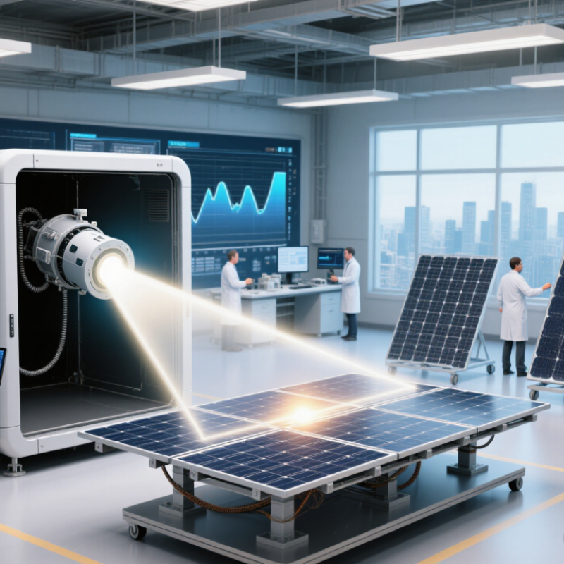
Space solar array simulators recreate the sunlight that reaches satellites above Earth’s atmosphere. They use xenon lamps, LED arrays, or combined light sources to match the AM0 spectrum. Modern orbital designs commonly use about 1,361 watts per square meter. However, older reference tables may list 1,366 watts per square meter. This difference matters during efficiency testing. ISO 21348 and ASTM E490 provide widely used solar spectral reference data.
A simulator also controls beam direction, uniformity, pulse stability, and panel temperature. A collimated beam can imitate sunlight arriving nearly parallel from the Sun. Thermal-vacuum testing adds cold walls, low pressure, and controlled heat rejection.
IEC 60904-9 evaluates spectral match, spatial non-uniformity, and temporal instability. These measurements help engineers compare results between facilities.
The setup must also reproduce realistic angles, because a few degrees can change output. The geometry matters.
A perfect orbital replica does not exist. Lamp aging can shift intensity, while reflections can create bright spots across a large array. Calibration therefore needs reference cells, irradiance sensors, and repeatable procedures.
In practice, some teams overfocus on light spectrum and undercheck thermal balance. That is a weakness worth admitting. Reliable simulators combine optical data, electrical measurements, and environmental records before accepting array performance.
Top Space Solar Array Simulators for Global Buyers
A space solar array simulator reproduces the electrical behavior of photovoltaic panels without exposing hardware to sunlight. Its main component is a programmable DC power system. It creates controlled voltage and current profiles. A real-time control unit calculates the expected I-V curve from irradiance, temperature, and mission data. This curve changes continuously during testing.
The system also needs voltage and current sensors, a switching matrix, protection circuits, and data-recording software. These parts work together during battery charging, load changes, and eclipse simulations. Engineers can test maximum power point tracking, start-up behavior, and abnormal conditions safely. Accurate calibration matters. Even a small sensor error can distort efficiency readings. Traceable instruments and independent verification improve confidence, although no model perfectly represents every space environment.
Tips: Check response speed, output stability, isolation, and protection limits before purchase. Request evidence of calibration. Test the simulator with a known reference load. Cable resistance is easy to overlook. It can create misleading voltage drops. A practical acceptance test should include rapid irradiance changes, repeated power cycles, and communication loss. Leave room for future mission profiles. Some systems perform well today but lack flexible software later. That weakness may only appear after integration begins.
Core Components and Operating Principles of Solar Array Simulation Systems
This chart shows the representative current response of a simulated photovoltaic array at a fixed 100 V operating point. The model uses the standard reference irradiance of 1,000 W/m² and assumes 10 A output at that level; photocurrent is approximately proportional to irradiance. A solar array simulator reproduces this behavior through a programmable DC power stage, control system, voltage and current sensors, and feedback software.
Space solar array simulators reproduce sunlight for spacecraft testing under controlled conditions. Continuous simulators support long-duration exposure, thermal stabilization, and repeated power measurements. Pulsed systems deliver intense flashes, making them useful for rapid I-V curve testing. LED-based systems offer adjustable spectra and lower operating heat, but their calibration can be more demanding. NASA lists the solar irradiance near Earth as about 1,361 W/m², a key reference for testing at one astronomical unit.
Different missions require different simulator architectures. A small satellite may need a compact LED chamber for array efficiency and deployment checks. Larger spacecraft often require a high-uniformity continuous source inside a thermal-vacuum facility.
The ESA Space Environment Report 2024 highlights changing radiation and solar activity conditions, so buyers should test more than nominal performance. Spectral mismatch, beam nonuniformity, and chamber reflections can distort results. These details matter.
Do not trust brightness alone.
Experienced test teams verify calibration with traceable reference cells, thermal sensors, and periodic mapping. NASA’s Small Spacecraft State of the Art reports emphasize power generation as a core spacecraft subsystem concern, especially for constrained platforms. I would also question advertised accuracy without independent test records.
Simulator selection is imperfect; a highly sophisticated source may still fail if the fixture blocks sunlight or the array temperature drifts. For global procurement, serviceability, calibration support, chamber compatibility, and regional safety certification deserve the same attention as optical output.
Selecting a space solar array simulator requires more than comparing output power. Global buyers should examine waveform accuracy, voltage range, current stability, and response time. These factors affect how reliably the simulator reproduces changing sunlight conditions.
Look for equipment that supports programmable I-V curves, eclipse transitions, temperature variation, and fast load changes. A clear calibration record matters. Traceable measurements improve confidence during acceptance testing and audits. Check whether the system supports international voltage requirements and recognized electrical safety practices. Documentation should include test procedures, software guides, maintenance intervals, and error limits. Poor documentation creates delays.
Ask suppliers to demonstrate real operating conditions, not only maximum specifications. Request a live test with a representative solar array profile. Observe how quickly the simulator reacts to sudden load changes. Review noise levels, cooling needs, footprint, and installation requirements. These details can influence laboratory productivity more than headline power ratings.
After-sales support also deserves careful comparison. Confirm remote diagnostics, spare-part availability, training, and regional response times. A low purchase price may become expensive when engineers wait weeks for assistance. However, the most advanced system may exceed a smaller facility’s needs. This is where procurement teams often overestimate future requirements. A practical scoring matrix can compare performance, reliability, integration effort, service, and total ownership cost. Leave room for uncertainty. Test results may differ from supplier demonstrations. Wet-lab validation remains essential before final approval.
For global buyers, selecting a space solar array simulator requires more than comparing output power. A capable unit should reproduce controlled irradiance, spectrum, temperature, and electrical behavior. Look for stable irradiance across the test plane and repeatable results during long operating cycles. Details matter. Suppliers should provide calibration records, measurement uncertainty, and traceability to recognized national or international laboratories. Request evidence of compliance with relevant electrical safety, electromagnetic compatibility, and quality requirements. Ask for test reports, not broad promises. Support matters.
Integration depends on the complete test environment. Confirm voltage, current, connector, communication, and data logging requirements before purchase. Interfaces should match the array’s power conditioning equipment and measurement software. Remote diagnostics can reduce delays across time zones, but they cannot replace skilled local service. International buyers should check installation training, spare-part availability, response times, and language support. A written escalation process is valuable. Not always.
Some suppliers focus heavily on specifications while underexplaining practical operation. This deserves careful review. A factory acceptance test can expose unstable readings, cooling problems, or software gaps before shipment. Request sample data from comparable operating conditions, then compare it with your own acceptance criteria. Verify thermal behavior, calibration intervals, and recovery after power interruptions. If documentation feels incomplete, pause the evaluation. That hesitation is useful. Record every setting, connection, and test result during commissioning to protect measurement reliability later.
It recreates sunlight received by satellites above Earth’s atmosphere. The target spectrum is commonly AM0. Modern reference conditions often use about 1,361 watts per square meter.
Systems may use xenon lamps, LED arrays, or combined light sources. Each approach has different spectral and control characteristics. No single light source is perfect.
Satellite sunlight arrives from a nearly fixed direction. A collimated beam imitates this geometry. Even a few degrees can change array output noticeably.
Thermal-vacuum testing can add cold walls, low pressure, and controlled heat rejection. The system may also simulate temperature changes and eclipse transitions. Thermal balance needs attention.
Engineers use reference cells, irradiance sensors, and repeatable procedures. They also check spectral match, spatial uniformity, and temporal stability. Lamp aging can slowly change intensity.
Some teams focus heavily on spectrum but undercheck thermal balance. Reflections can create bright spots across a large array. That weakness deserves honest review.
Review programmable current-voltage curves, voltage range, current stability, and response time. Check eclipse transitions, temperature variation, and fast load changes. Maximum power alone is not enough.
Request a live demonstration with a representative solar array profile. Observe sudden load changes, cooling needs, noise, footprint, and installation demands. Supplier demonstrations may not match laboratory results.
Clear procedures, software guides, maintenance intervals, and error limits reduce delays. Remote diagnostics, training, spare parts, and regional response times also matter. A low purchase price can become expensive later.
Use a scoring matrix covering performance, reliability, integration effort, service, and ownership cost. Leave room for uncertainty. Wet-lab validation remains essential before final approval.
Space Solar Array Simulators are specialized test systems designed to reproduce the light intensity, spectral characteristics, and operating conditions that spacecraft solar panels experience in orbit. By combining calibrated light sources, optical control, power electronics, monitoring instruments, and thermal management, these simulators enable engineers to evaluate electrical output, efficiency, degradation, and system performance under controlled conditions. Their operating principles support repeatable testing without relying on unpredictable outdoor sunlight or actual space missions.
Different simulator types serve different purposes, including laboratory research, component qualification, full-panel testing, and integrated spacecraft validation. For global procurement, buyers should compare spectral accuracy, illumination uniformity, adjustable power levels, test-area dimensions, measurement precision, automation, and compatibility with existing facilities. Attention should also be given to recognized testing standards, calibration procedures, documentation, installation requirements, training, maintenance, and after-sales technical support. A well-selected system can improve testing reliability, shorten development cycles, and support consistent solar array evaluation across international engineering teams.