Power Electronics Blog & Articles
In-depth technical guides, engineering innovations, and testing methodologies from AMETEK Programmable Power specialists.
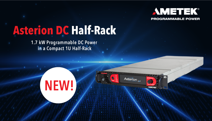

Discover best practices for bidirectional power supply integration and regenerative grid simulation testing.
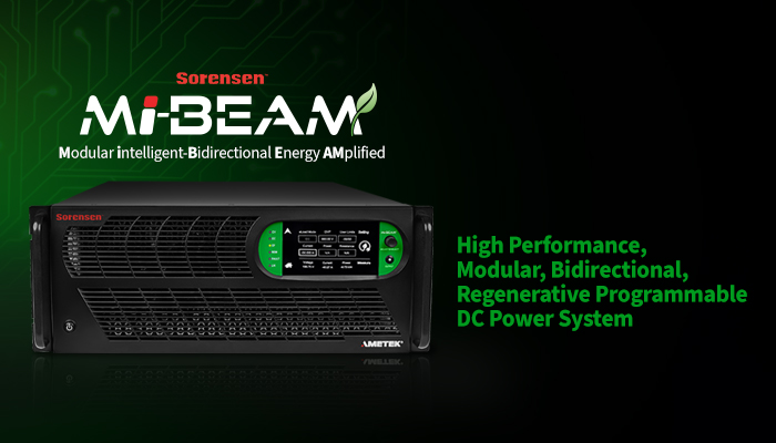
Learn how advanced MPPT algorithms and solar array simulators improve power subsystem testing for aerospace applications.
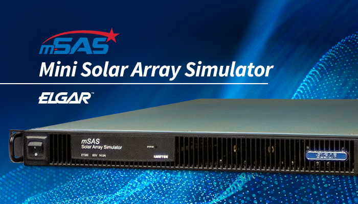
Choosing Regenerative Grid Simulators is not a simple comparison of power ratings and price tags. These systems reproduce grid conditions while returning absorbed energy to the facility. That makes them valuable for testing inverters, converters, storage systems, electric vehicles, and protection controls. It also makes poor selection expensive. A simulator may look impressive on a brochure, yet respond too slowly during a voltage sag.
Power-electronics expert Professor Frede Blaabjerg has described power electronics as “the enabling technology for renewable energy systems.” His observation remains relevant here. A capable simulator must connect renewable-energy ambitions with measurable laboratory performance. Buyers should examine voltage and frequency ranges, four-quadrant operation, regenerative efficiency, transient response, harmonic control, and programmable grid faults. Safety functions matter equally. Interlocks, isolation, emergency shutdown, and clear thermal limits protect both equipment and personnel.
Start with the test objective. A photovoltaic inverter lab may need fast harmonic reproduction, while an electric-vehicle charger lab may prioritize bidirectional power flow. Consider the supply infrastructure, cooling capacity, noise, software interface, and available floor space. A 100 kVA unit can require more practical planning than expected.
Specifications can mislead.
Ask for real waveforms, not only nominal values. Request application references, factory-test evidence, calibration information, and service response commitments. A regenerative system should also state how much energy it returns under changing loads. Efficiency at one operating point is not enough.
This guide explains how to compare Regenerative Grid Simulators through performance, integration, safety, and long-term reliability. The evaluation is not perfect. Laboratory priorities change, and published data may omit inconvenient details. That uncertainty deserves attention before any purchase decision.
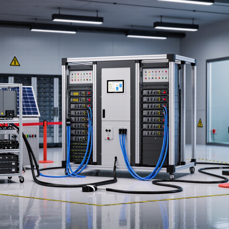
How to Choose Regenerative Grid Simulators?
Define the Application, Grid Conditions, and Testing Objectives
Choosing a regenerative grid simulator starts with the equipment under test. A motor drive, inverter, or energy storage system may need different voltage and current profiles. Define the intended application before comparing specifications. In a laboratory, I would record nominal voltage, maximum power, operating frequency, and expected transients. A clean test plan prevents expensive surprises. However, real systems rarely behave perfectly.
Grid conditions deserve equal attention. Check whether the simulator can reproduce voltage dips, frequency changes, phase imbalance, harmonics, and rapid transitions. Confirm its regenerative capability when the test system returns energy. The power flow should remain stable, even during repeated acceleration and braking cycles. Also examine measurement accuracy, response time, protection functions, and cooling requirements. A simulator that looks powerful on paper may struggle during a long thermal test.
Tips: Match the simulator’s rating to actual test conditions, not only peak values. Leave reasonable headroom for startup surges and fault recovery. Test cables, filters, and control software as one system. Keep a written record of waveform settings and observed deviations. Small details matter. If the test objective is unclear, pause before purchasing. I have seen teams select advanced equipment without defining pass-and-fail limits. That decision created excellent data, but not useful evidence. Review the plan with a qualified engineer, and revise it after the first trial.
Select the simulator from the test objective, not the brochure headline. Define continuous power, peak power, voltage range, and current first. IEA’s Renewables 2024 report recorded nearly 510 GW of renewable capacity additions in 2023. That rapid growth increases the need for flexible grid testing.
A simulator should reproduce normal operation and sudden events. Check whether it supports 50 Hz, 60 Hz, and programmable frequency changes. Voltage accuracy also matters. Small errors can distort inverter efficiency and protection results.
Bidirectional capability is essential for modern energy systems. It allows the simulator to source power and absorb returned energy. This resembles batteries, electric vehicles, and regenerative industrial loads.
IRENA reported 473 GW of renewable capacity added globally in 2023. More variable generation means more tests involving voltage dips, frequency shifts, and reverse power flow. Confirm the regenerative rating, not only the output rating. A unit may deliver high power but absorb much less. That difference can invalidate a test plan.
Tips:
Match continuous and short-duration ratings to your equipment. Ask for response time, harmonic distortion, and overload behavior. Test the full voltage range before purchase. In practice, engineers often underestimate cable losses and cooling requirements. I have seen simulations fail because the power rating looked sufficient on paper. That assumption deserves review. Also verify measurement synchronization and fault-recording functions. Clear data is as important as electrical strength.
How to Choose Regenerative Grid Simulators?
A regenerative grid simulator should reproduce power flow in both directions. That detail matters during battery discharge, inverter testing, and braking-energy recovery. Compare regenerative performance by checking maximum returned power, response time, and energy efficiency. Ask whether the system controls voltage, frequency, current, or power directly. Practical testing often exposes small delays that brochures do not show. A fast response is useful, but stable control matters more when the load changes suddenly.
Tips: Request measured waveforms, not only rated values. Test a repeated charge-and-discharge cycle. Watch for voltage overshoot, audible switching noise, and unexpected thermal changes. Keep the test setup consistent. Otherwise, comparisons become weak.
Control modes should match your application. Constant-power mode suits grid emulation and inverter evaluation. Constant-voltage mode helps examine charging behavior. Current control can reveal protection thresholds more clearly. Simulation accuracy depends on sensors, sampling speed, control algorithms, and model quality. Validate the simulator against an independent meter and a known reference load. Small errors may seem harmless, yet they can change efficiency results over long tests. No simulator is perfectly realistic. That is worth remembering. I would also document failed trials, because an unstable waveform may reveal a model limitation rather than a hardware defect. A reliable selection process values repeatability, transparent specifications, and accessible calibration records.
| Evaluation Dimension | Entry-Level Configuration | Industrial General-Purpose Configuration | High-Performance Research Configuration |
|---|---|---|---|
| Typical AC Power Rating | Approximately 3–30 kVA | Approximately 30–300 kVA | Approximately 300 kVA–1 MVA or higher |
| Output Voltage Range | Commonly up to 300–400 V line-to-line | Commonly up to 480–690 V line-to-line | Configurable for medium-voltage interfaces through an external transformer |
| Output Frequency | Typically 45–65 Hz; selected models support wider ranges | Typically 15–100 Hz or wider, depending on operating mode | Often from DC or a few hertz to several hundred hertz, subject to voltage and power limits |
| Regenerative Operation | May be available; verify whether returned energy is fed back to the utility | Bidirectional four-quadrant operation is commonly available | Designed for continuous source-and-sink operation with programmable energy flow |
| Regenerative Efficiency | Usually about 85–93% when regeneration is supported | Typically about 90–96% under rated operating conditions | Typically about 94–98%; actual results depend on load, power factor, and switching conditions |
| Current Control | Constant-current and current-limit functions | Constant-current, peak-current, and programmable current profiles | Closed-loop arbitrary waveforms, sequence control, and fast transient-current control |
| Voltage Control | RMS voltage and basic ramp control | RMS, peak, phase-angle, ramp, and sequence control | Independent phase control, arbitrary waveforms, harmonics, dips, swells, and rapid transients |
| Operating Modes | AC source, DC source, and basic load testing | AC source, DC source, grid emulation, electronic load, and regenerative load | Grid-following, grid-forming, islanded microgrid, impedance emulation, and hardware-in-the-loop modes |
| Power Factor Capability | Often limited to near-unity power factor operation | Programmable leading and lagging power factor, commonly down to approximately 0.8 | Four-quadrant reactive-power control, commonly covering approximately −1 to +1 power factor |
| Waveform and Disturbance Simulation | Basic sine-wave generation and voltage ramps | Harmonics, unbalance, voltage dips, swells, interruptions, and frequency steps | Point-on-wave events, interharmonics, flicker, custom fault sequences, and real-time grid profiles |
| Dynamic Response | Usually suitable for steady-state and slower transient tests | Typically suitable for millisecond-scale voltage and current changes | Designed for sub-millisecond to millisecond-scale transients; confirm the specified settling time |
| Voltage Accuracy | Commonly around ±0.5–1.0% of full scale | Commonly around ±0.1–0.5% of full scale | Often better than ±0.1% of full scale under defined calibration conditions |
| Frequency Accuracy | Typically approximately ±0.05–0.1 Hz | Typically approximately ±0.01–0.05 Hz | Often approximately ±0.001–0.01 Hz, depending on the operating range |
| Total Harmonic Distortion | Typically below 2–3% with a linear load | Typically below 1–2% with a linear load | Often below 1%, subject to bandwidth, output filter, and load conditions |
| Simulation Accuracy Considerations | Adequate for functional checks and basic compliance pretests | Suitable for repeatable product validation and most laboratory test sequences | Suitable for model validation, grid-code studies, converter control testing, and real-time co-simulation |
| Measurement and Feedback | Built-in RMS voltage, current, power, and frequency readings | Adds waveform capture, power-quality measurements, and programmable logging | High-speed synchronized sampling, external sensors, real-time feedback, and automated data acquisition |
| Control and Communication Interfaces | Front-panel control, USB, and basic remote commands | Ethernet, USB, analog I/O, and common automated-test interfaces | Real-time Ethernet, deterministic I/O, fieldbus integration, scripting, and hardware-in-the-loop interfaces |
| Best-Fit Applications | Education, small power supplies, basic inverter tests, and general laboratory use | Renewable-energy converters, EV power electronics, UPS systems, motor drives, and production validation | Grid-code verification, microgrid research, advanced converter controls, protection studies, and real-time simulation |
Note: The values shown are representative industry ranges rather than specifications for a particular product. Final selection should be based on the complete datasheet, measurement bandwidth, calibration conditions, overload capability, regeneration duty cycle, applicable grid standards, and required test profile.
How to Choose Regenerative Grid Simulators?
A regenerative grid simulator should protect people, equipment, and test data. Check emergency stops, output isolation, overvoltage limits, and automatic fault shutdowns. Safety interlocks should prevent energizing an open cabinet or disconnected load. Clear alarms matter. A technician should understand the fault within seconds, not search through hidden menus. Review fault logs, access controls, and recovery procedures during a live demonstration. Safety claims require evidence.
The interface should show voltage, current, frequency, phase angle, and power flow together. Large values help, especially during stressful commissioning work. Confirm whether operators can create ramps, disturbances, and repeatable test sequences without complex coding. The software should support scripting, data export, version control, and permission management. Test engineers need traceable results. A convenient screen is not enough. Sometimes, advanced menus slow down real work.
Tips: Connect the simulator to your actual controller, protection device, and communication network before buying. Test common protocols, timing behavior, and signal scaling. Ask for a sample waveform and compare it with your measurement equipment. Check how the system behaves after a communication loss. It should enter a defined safe state. Integration often fails at small details, such as connector pinouts or clock differences. Leave time for training. Even reliable software can confuse new operators. Review the full setup with an experienced engineer, then document what still feels uncertain.
Choosing a regenerative grid simulator requires more than checking voltage range and waveform accuracy. NERC’s 2024 Long-Term Reliability Assessment projects North American summer peak demand to grow 15% within ten years. That growth increases the need for repeatable testing under stressed conditions.
Verify power recovery efficiency, transient response, channel synchronization, and fault injection depth. Ask for measured results, not brochure claims. A simulator should reproduce weak-grid behavior, harmonics, islanding, and renewable intermittency without overheating during long tests.
Support and compliance also shape reliability. Confirm documented alignment with IEC 61850, IEEE 1547, and applicable regional grid codes. Request calibration certificates, software version control, cybersecurity procedures, and response-time commitments.
The International Energy Agency’s Electricity 2024 report expects global electricity demand to grow by more than 4% in 2024 and 2025. Testing platforms must therefore support changing interconnection requirements.
Total ownership cost includes integration labor, cooling, floor space, energy consumption, licensing, maintenance, and downtime. A cheaper unit can become expensive after repeated firmware issues. I have seen teams underestimate engineering support. That mistake is avoidable.
Tips:
Perfect specifications can still hide inconvenient assumptions.
Record nominal voltage, maximum power, operating frequency, and expected transients. Define clear pass-and-fail limits.
Continuous power supports long tests. Peak power handles short surges, acceleration, braking, and fault recovery.
The simulator can supply power and absorb returned energy. This supports batteries, vehicles, inverters, and regenerative loads.
Check for voltage dips, frequency changes, phase imbalance, harmonics, and rapid transitions. Normal operation alone is not enough.
Confirm 50 Hz, 60 Hz, programmable frequency changes, and the full voltage range. Small errors can distort protection results.
Look for emergency stops, output isolation, overvoltage limits, interlocks, and automatic fault shutdowns. Alarms should be easy to understand.
Useful functions include ramps, disturbance sequences, scripting, data export, version control, and permission management.
Connect the simulator to controllers, protection devices, cables, filters, and networks. Small timing or connector errors can disrupt testing.
Very important. A unit may meet peak specifications but struggle during a long thermal test.
Choosing advanced equipment before defining the test objective can produce impressive data, but weak evidence. The plan may need revision.
Choosing Regenerative Grid Simulators begins with clearly defining the intended application, operating environment, grid conditions, and testing objectives. Consider whether the simulator can reproduce the required voltage, power, frequency, phase behavior, and bidirectional energy flow. Its regenerative capability should support efficient energy recovery while maintaining stable operation under changing loads and grid events. Compare available control modes, waveform quality, response speed, and simulation accuracy to ensure the system can represent real-world conditions with confidence.
The evaluation should also include electrical and operational safety features, protection functions, communication interfaces, software usability, data recording, and compatibility with existing test equipment. A practical solution should be easy to integrate, configure, monitor, and expand as testing requirements develop. Finally, assess long-term reliability, maintenance needs, technical support, regulatory compliance, training, and total ownership cost. Looking beyond the initial purchase price helps organizations select a simulator that delivers dependable performance, efficient testing, and sustainable value throughout its service life.